Compressor Limiter 01 - The World of Free Packet Software Amsterdam
Here Can You Find A Schematic of A Audio Compressor Limiter - Compressor Limiter 01 of 06
FREE CONTENTS WELCOME IN THE WORLD OF FREE PACKET RADIO SOFTWARE AMSTERDAM THE NETHERLANDS
 
Arrow HOMEPAGE
 
Arrow 11 Meter
Arrow 2 Meter To 10 Meter
Arrow 3 Meter BLX 15
Arrow 4 Meter
Arrow 60 Cm Convertor
Arrow 60 Cm Transmitter
Arrow 70 Cm Convertor
Arrow 70 Cm Antenna 01
Arrow 70 Cm Antenna 02
Arrow Active Antenna
Arrow Auto Squelch
Arrow Baycom Modem 01
Arrow Baycom Modem 02
Arrows COMPRESSOR LIMITER 01
Arrow Compressor Limiter 02
Arrow Compressor Limiter 03
Arrow Compressor Limiter 04
Arrow Compressor Limiter 05
Arrow Compressor Limiter 06
Arrow Data Carrier Detect
Arrow Dip Meter
Arrow Field Strength Meter 01
Arrow Field Strength Meter 02
Arrow Generator
Arrow Interface 01
Arrow Interface 02
Arrow Rtty Base
Arrow Rtty Tnc
Arrow Schematics
Arrow Tvi Filter
Arrow Tnc 2c 01
Arrow Tnc 2c 02
Arrow Tnc 2c 03
Arrow Tnc 2c 04
Arrow Tnc 2c 05
Arrow Tnc 2c 06
Arrow UAA 170 VU Meter
Arrow UAA 180 VU Meter
Arrow Universal VU Meter
Arrow Yagi
Arrow Webmasters

An Search Engine Using A Proprietary Page Ranking

ACTIVE SEARCH RESULTS


Do You Need Targeted Visitors, Get Now 200 Free Visitors.

YOU NEED TARGETED VISITORS
GET NOW 200 FREE VISITORS


Ziggo High Speed Fiber Power - Download Speed 200 MB/s And Upload Speed 20 MB/s

ZIGGO HIGH SPEED FIBER POWER
DOWNLOAD SPEED: 200 MB/s
UPLOAD SPEED: 20 MB/s


THE WORLD OF FREE PACKET RADIO SOFTWARE AMSTERDAM

HERE CAN YOU FIND A SCHEMATIC OF COMPRESSOR LIMITER 01


THE AUDIO COMPRESSOR LIMITER

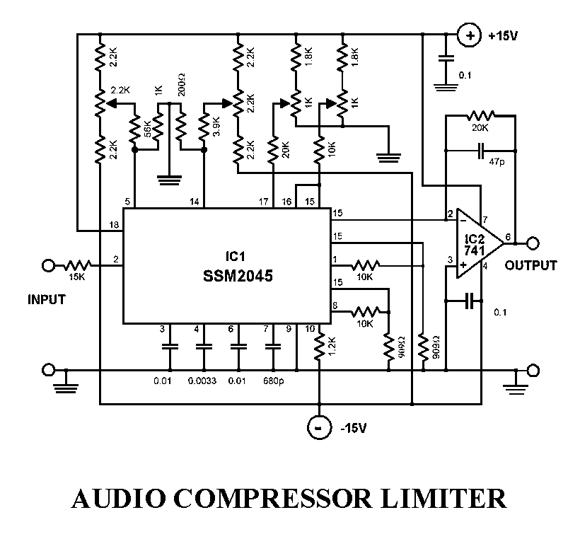
This audio processor circuit features the SSM2045 IC which was developed specially for electronic music applications and the 741 opamp IC. The circuit is configured as a low pass filter with a DC voltage control for gain. The input signal is set to a working level of 150 mV pp through the resistor R1.

HOW DOES THIS AUDIO COMPRESSOR LIMITER WORK:

The filter has 2 buffered outputs the 2-pole output at pin 1 and 4-pole output at pin 8. Internally, the outputs are connected to 2 voltage-controlled-amplifiers (VCA). The R15 and R16 are connected to these outputs to achieve optimum offset and control voltage suppression. P4 is the volume control. The current that flows to the pins 15 and 16 should not go beyond the maximum of 250 A. The balance of the two VCAs and the entire filter is being controlled be a voltage range of -250 mV to + 250 mV at pin 14. This voltage can be set by P2. The input can be driven with source impedances up to a maximum of 200 Ω. With an input level of 0dBm, the VCA weakens by 6 dB. The bias current needed at pin 17 is between 120 A and 185 A. The cutoff frequency can be shifted between 20 Hz and 20 kHz with a variable voltage at pin 5. This can be varied through P1. The capacitor values were selected to give the filter its Butterworth characteristics. The output current of the SSM2045 IC is converted to a voltage output by the 741 opamp. Any subsequent circuit must be DC decoupled from IC2. The noise voltage ration is about 80 dB.


Audio Compressor Limiter - Page 01

SCHEMATIC FROM A AUDIO COMPRESSOR LIMITER - EXAMPLE 01 OF 06


THE WWW.ALWAYSFREE.NL WEB REPUTATION


Do you need targeted visitors, get now 200 free visitors.

DO YOU NEED TARGETED VISITORS TO YOUR WEBSITE, GET NOW 200 FREE VISITORS


2 GB Storage That You Get At Free Web Hosting From www.hostinger.co.uk

FREE WEBSITE HOSTING IN UK WITH PHP AND MYSQL, WEBSITE BUILDER, NO ADS


Submit Here Your Website To The Web's Top 50 From Search Engines for Free

SUBMIT YOUR WEBSITE TO THE TOP 50 OF THE BEST SEARCH ENGINES FOR FREE


The World of Free Packet Software in Amsterdam.
The World of Free Packet Radio Software Amsterdam The Netherlands.

The World of Free Packet Software in Amsterdam The Netherlands - All Rights Reserved.